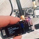
TTGO T-Beam: where is power led?
If you were trying to work with TTGO upper-grade devices, chances you had questions about their peripherals. Even with Internet they are not so easy to solve, as it seems at first:
- how to manage power sink to board hardware, wifi bt gps ynameit,
- what are power control pins (spoiler:none exist),
- how to enable honest low-power modes, and
- what/where is that f* Power Led pin?
T-Beam does not have exact power LED, but have power control LED, by default bright blue, and GPS operation LED, by default dull red. There’s no green LED as some docs say. Earlier boards do have, T-Beam do not.
Fortunately, I’m here to give you some answers and clarity. But it’s really strange for me that Stackoverflow and Github have basically no information, despite the fact the answer is pretty straightforward, just need to take a long precise look onto your board.
(Our Chinese friends are not so quick at all, when talking about docs.
You probably already noticed that, sad but true).
On earlier and simpler ESP32-based TTGO boards, BUILTIN_LED has to be connected to ESP pins, 2 or 14. Or 17, as wiki said. But it’s a harsh lie :)
Truth is: T-Beam uses auxillary power manager, hardware AXP192. Look for a second on your board, you’ll easily find one.
Even more, AXP is now in charge for all power distribution, DCDCs, voltage refs, powering and managing all peripherals, and even for charging process itself. Why? Because it’s pretty hard to do that directly via power control pins for every simple stuff on board, and AXP does this easily & seamless using only serial interface. So c’mon, things are not so bad at all, just no docs and some blackbox flavor.
AXP even has the IRQ mappings so you can receive an irq_event when, for instance, device power changes.
So, there are no power pins, and code like this will not work:
pinMode(BUILTIN_LED, OUTPUT); // not working
digitalWrite(BUILTIN_LED, HIGH); // not working
Instead, the simpliest part, powering the power LED:
#include <axp20x.h>
AXP20X_Class axp;Wire.begin(21, 22);
axp.setChgLEDMode(AXP20X_LED_LOW_LEVEL);
Note we are using AXP library by Lewis He, which provides access to all serial communication with board’ power control. There should be no issue linking it into your project, if you take a look at native GPS examples, there already lies some code related— GPS chip is powered via AXP just like any other chip onboard.
For LED, AXP already have some default modes implemented — like blink, so you don’t have to spare CPU cycles on this:
axp.setChgLEDMode(AXP20X_LED_OFF); // LED off
axp.setChgLEDMode(AXP20X_LED_BLINK_1HZ); // 1blink/sec, low rate
axp.setChgLEDMode(AXP20X_LED_BLINK_4HZ); // 4blink/sec, high rate
axp.setChgLEDMode(AXP20X_LED_LOW_LEVEL); // LED full on
Nice, isn’t it?
AXP gives all necessary controls for power distribution. It’s a good practice to check if AXP is alive (ah, Chinese hardware!), and after that power up all the stuff you may need:
if (!axp.begin(Wire, AXP192_SLAVE_ADDRESS)) {
    Serial.println("AXP192 Begin PASS");
} else {
    Serial.println("AXP192 Begin FAIL");
}
axp.setPowerOutPut(AXP192_LDO2, AXP202_ON);  axp.setPowerOutPut(AXP192_LDO3, AXP202_ON);  axp.setPowerOutPut(AXP192_DCDC2, AXP202_ON);  axp.setPowerOutPut(AXP192_EXTEN, AXP202_ON);  axp.setPowerOutPut(AXP192_DCDC1, AXP202_ON);
Few words about peripherals: maybe i’ll add more precise examples later, buth the main story is the same — AXP controls modes even for ESP32 itself. So speaking for low-power modes and sleep cycles, be sure to adjust power first, or even switch off (or on) all unnecessary stuff:
| CHIP     | AXP173           | AXP192           | AXP202
| -------- | ---------------- | ---------------- | ----------------
| DC1      | 0v7~3v5  /1200mA | 0v7~3v5  /1200mA | X
| DC2      | 0v7~2v275/1600mA | 0v7~2v275/1600mA | 0v7~2v275/1600mA
| DC3      | X                | 0v7~3v5  /700mA  | 0v7~3v5  /1200mA
| LDO1     | 3v3      /30mA   | 3v3      /30mA   | 3v3      /30mA
| LDO2     | 1v8~3v3  /200mA  | 1v8~3v3  /200mA  | 1v8~3v3  /200mA
| LDO3     | 1v8~3v3  /200mA  | 1v8~3v3  /200mA  | 0v7~3v3  /200mA
| LDO4     | 0v7~3v5  /500mA  | X                | 1v8~3v3  /200mA
| LDO5/IO0 | X                | 1v8~3v3  /50mA   | 1v8~3v3  /50mA
For example, if you forced to wait some time with CPU only, you can cut peripherals and lower ESP32 power in half, to 1.8V (1800mV)
axp.setDCDC1Voltage(1800);
axp.setDCDC3Voltage(1800);
But take note that low-power mode means every additional current sink from ESP pins itself may lead the device to become unstable. Pull it up back again first when switching back to normal operation.
Pinout:
- DCDC3 — power 3.3V to the board
- DCDC1 — power to OLED pins + some other
- LDO2 — LORA power
- LDO3 — GPS power (NEO chip)
- DCDC2 used as DCDC for your needs, in V8
Power-on routines are also replaced by programmed AXP logic, since AXP already controls all power management and actually is powered up unconditionally before any other chip or ESP32 itself
(or instead, note there’s no slave TP5400 anymore).
But this looks like a topic for another post.
Last, about power consumption with AXP. Expect estimates like these:
- Operation modes — 40..50 mA
- Power LED — another 20 mA sink
- Deep Sleep — 5..8 mA varied by IRQ & timer
Hope that helps.
